| |
 |
|
| |
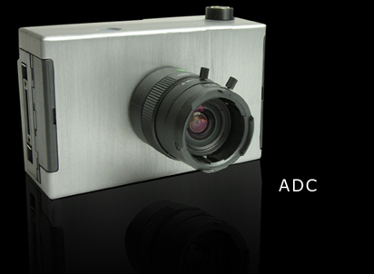
ADC
Tetracam's
LCD-Equipped
Agricultural Digital Camera
Note: This unit is no longer in production. *
Overview
*
PixelWrench2
*
Ground
Resolution and Field of View
*
System
Controls and Connections
*
Camera
Triggering
*
System
Contents
*
System
Availability
*
Options
*
System
Features and Specifications
*
Additional
Reference Information
*
Image
Examples
|
|
|
 |
| |
Overview
Tetracam's
Agricultural Digital Camera (ADC) sets the standard for multi-spectral
imaging of crop canopies and vegetation. The ADC boasts a
conventional digital camera's feel while delivering unparalleled
multi-spectral imaging capabilities.
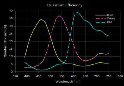
The ADC contains a single precision 3.2 megapixel image sensor
(storing 2048 x 1536 pixels)
optimized for capturing visible light wavelengths longer than 520nm and
near-infrared wavelengths up to 920nm. The image sensor is divided into
a mosaic of tiny optical filters. Each filter allows a separate red,
green or NIR band of wavelengths to pass while blocking
others. These are equivalent to TM2, TM3 and TM4 Landsat bands. PixelWrench2
PixelWrench2,
the image processing software included with the camera, enables
extraction of standard vegetation indices (such as NDVI, SAVI, canopy
segmentation and NIR/Green ratios) from the captured
images. Competing with images available from satellites,
the ADC offers lower-cost image capture, freedom from cloud cover and
the ability to readily obtain re-occurring images for timely
comparisons. Refer to
our
Multispectral Crop and Application Database or
Selected Readings for descriptions of
example applications.
The
ADC is GPS compatible and ideal for ground-based or airborne
operations. The unit's liquid crystal display provides the user
with the ability to observe the live image, menus for handheld use, and
color palletized vegetation indexed images. The same images available
on the LCD may be sent to a remote receiver. |
|
|
|
| |
ADC (with 8.0 mm Lens)
Ground Resolution & FOV Examples
The
ADC's field of view (FOV) is laid out in a 4:3 format. When
carried in a manned or unmanned aircraft, the field of view increases
as the above ground level (AGL) altitude increases. As the
AGL increases, the camera's ability to resolve individual details on
the ground decreases. With its standard 8.0 mm lens, when
flown at altitude of 400 feet above ground level, this camera creates
an image large enough to capture 1.85 acres at a resolution of less
than two inches per pixel in a single shot!
| Sensor & Lens Parameters |
Object Distance
(Altitude Above Ground Level in meters)
|
Ground Resolution
in mm per pixel |
FOV
(width x height)
in meters |
The
values shown at right were derived from the FOV (Field of View) Optical
Calculator contained in Tetracam's PixelWrench2 software (included with
this camera) using the current values for this camera shown
below:
Sensor Dimensions (mm): 6.55 x 4.92
Pixel Size (in microns): 3.2
Camera Lens Focal Length (mm): 8.0 |
122 m (~ 400 ft) |
48.8 |
100 x 75 |
213.4 m (~ 700 ft) |
85.4 |
175 x 131 |
365.8 m (~ 1200 ft) |
146.3 |
300 x 225 |
915 m (~ 3000 ft) |
366 |
749 x 563 |
System Controls and Connections

|
|
ADC Controls User
control of the ADC is accomplished through a hierarchical system of
menus such as the one shown at left. These are accessible via the
liquid crystal display and buttons on the back of the unit or through
the system software (PixelWrench2) running on a Windows computer
connected to the camera via its USB interface. The system menus present
users with a series of configuration choices. Scrolling through
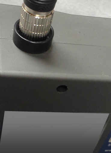
and selecting these configures the camera. The button
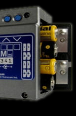
on top of the ADC acts as a shutter release.
When this button is pressed down, the system
captures an image. The shutter button
contains a circular Hirose connector (shown at
left). This connector enables the camera to
be connected to an accessory ADC/MCA Test Control
box (pictured below) or to un-terminated wires
that users may connect to other external devices.
|
|
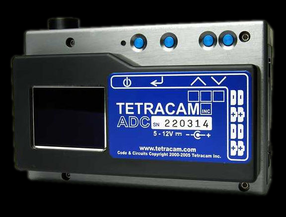
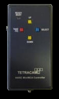
ADC/MCA
Controller Box Accessory -The optional ADC/MCA Controller Box (shown at
left) contains buttons that enable the user to manually scroll up and
down through system menus, pick a selection or take a picture.
The box also contains an RS232 connector and a Video Out
connector. These may be linked to the camera through the circular
Hirose Multi-I/O Connector atop the shutter. Information on the
ADC's Multi-IO Hirose circular connector and the cables that may be
connected to it are shown on our web site here. |
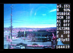
The ADC's daylight-viewable liquid crystal display possesses a high
definition 16:9 aspect ratio. In operation, the camera's
viewfinder is flanked by an information panel which shows the state of
the device without having to access system menus. The items that are
displayed during normal operation on the right side of the screen
include:
- Firmware version
- Battery % charge
- USB mode USBDSK/USBCAM
- File format mode DCM/RAW8/RAW10
- Alarm setting OFF/ON
- Continuous Capture ON/OFF
- Available memory on CF card
- Picture counter
- Exposure AUTO/FIXED, Exposure +/- setting
- Average and Peak Brightness values (%)
- Viewfinder image histogram
- Current Time
|
 |
|
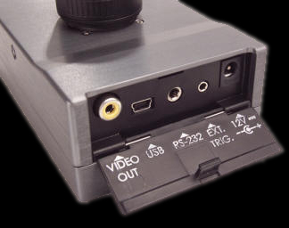
ADC Connections
The
ADC obtains its power from a 12 VDC external power supply provided with
the unit. This plugs into the 12V power input on the side of the
chassis. The system is also able to be powered by means of
eight AA alkaline batteries inserted into the opposite side of the
chassis.
The camera contains a Video Out connector that may be used
to feed the same images available on the LCD to a remote receiver via a wire or telemetry. |
|
 |
To
the right of the Video Out connector, the USB connector provides a link
to host computers. PixelWrench2 can process images accessed via
this link or the CF card containing the images may be pulled from the
camera and inserted to the computer containing PW2. The camera
contains an RS232 link that may be connected to a GPS receiver for
capturing the precise GPS coordinates at the exact instant that an
image is captured. Lastly, the camera contains a external Trigger
connector. An External Trigger Cable (un-terminated on one end)
is available with the system for remotely triggering the camera to
capture images. Closing the connection between the RING and the
TIP on the provided cable causes the camera to trigger (reference TYPICAL EXTERNAL TRIGGER CIRCUIT for further details). The ADC may also be triggered in a variety of other ways - see below. Check out the User Manual below for precise descriptions of the system menus and all other controls and connections in the ADC.
Standard System Contents
| |
System Contents Includes:
ADC
Camera and 8.0 mm Lens
2GB CF card
USB Cable
AC/DC power supply
White Teflon Calibration Plate (AKA Calibration tag or
Software Calibration Tile)
8 AA batteries
Rugged carrying case
System CD with PixelWrench2 software (PW2)
(See additional CD contents at right)
Typical Availability:
2 to 3 weeks
(although faster turnaround times are often possible). Please
contact us
for more information regarding configuration options, pricing and availability.
Options Commonly
Purchased with this
Product:
|
|
List of files on included System CD: 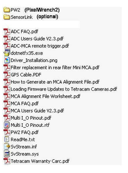
|
Features and
Specifications |
|
| |
 Features Features |
|
 Specifications Specifications |
|
| |
-
High resolution and precise spectral accuracy
- Simple operation and control
- Red, Green and NIR bands (approximating
TM2, TM3 and TM4) provide the information needed for extraction of NDVI, SAVI, canopy segmentation and NIR / Green ratios
- Video out in PAL or NTSC format
GPS-logging of captured images with external receiver
Daylight-viewable display
- User interchangeable optics
- Uses standard Compact Flash Memory cards (standard = 2 GB Optional = up to 256 GB)
- Powerful PixelWrench2 image editing
software with several tools specific to multi-spectral images and Tetracam cameras (see Tetracam Application Software Overview for further details)
-
Multiple Camera Triggering Methods
-
Shutter
Release: The button atop the ADC acts as a shutter release for
the camera. Depressing the button triggers the camera to take a
picture.
-
Auto-Timer
(Continuous Capture Mode): The ADC may be configured to capture images continuously at intervals
specified by the user via the camera's system menus.
Press the Shutter Release or trigger the camera via one of the methods
below to begin continuously capturing images. Press the Shutter
Release or trigger the camera again to stop continuous capture of images.
Always stop continuously capturing images by pressing the Shutter Release
or via a trigger command prior to powering the camera off.
Interruption of power during continuous capture of images may damage the
camera.
-
Computer Triggering: The camera may be triggered through its USB interface. Optional GetShot software enables remote triggering
under command of a linked computer. Optional
SensorLink
GPS waypoint triggering
application enables camera triggering at pre-defined waypoints - a popular method used in manned aircraft.
-
Optional Remote Shutter Release:
Closing
the connection between the RING and the TIP on an optional External
Trigger Cable causes the camera to trigger (reference TYPICAL EXTERNAL TRIGGER CIRCUIT for further details).
-
RS-232
Triggering: The camera may be commanded to trigger by receiving
an <ESC> T command via its RS232 serial interface. Due to
the delays incumbent in a serial link, the RS232 link is more commonly
used to transfer GPS position coordinates to the camera at camera
trigger time. When the camera is connected to a GPS receiver via its
RS232 link, the camera records the coordinates of the location at which
each image is captured into its log file upon receiving any camera
trigger command.
-
Superior Low Noise Image Sensor
|
|
-
3.2 megapixel CMOS
sensor (2048 x 1536 pixels)
-
Image storage to Compact Flash memory cards in Tetracam 10 bit DCM lossless, 8 bit RAW, and 10 bit RAW formats.
-
Image Capture
Capacity:
Up to
~3 MB per image (DCM format), limited only by CF card size.
-
Maximum Image
Capture Rate: Approximately 1.0 to 7.5 Seconds between
consecutive images depending upon image format and resolution selected - See
Interval
Tables
-
Tough CNC machined aluminum housing.
-
CS lens mount system compatible with thousands of available lenses.
-
Camera supplied with a 8.0 mm lens
Optional 4.5 - 12 mm varifocal lenses may be substituted
-
Power Source options:
Battery - (8) AA size batteries.
External Power Supply +9 VDC to + 12 VDC (300 mA)
-
Inputs:
+ 9 VDC to +12 VDC (300 mA current rating) Center Positive
RS-232 dedicated to capture of NMEA GPS sentences.
External Trigger, USB,
Multi-IO connector (built into shutter release).
-
Power Consumption
Two watts nominal
-
Outputs:
Real time NTSC or PAL Video for both viewfinder and menu operations.
-
Data Interface:
USB 1.1
-
Environmental
- Note: the camera will
operate outside of the recommended environmental range, however
performance may be degraded.
-
Temperature
0 degrees Celsius to 40 degrees Celsius (32 degrees Fahrenheit to 104
degrees Fahrenheit)
-
Humidity
Less than 85% relative humidity, non-condensing
-
Dimensions:
4.8 in. x 3.0 in. x 1.6 in. (122 mm x 78 mm x 41 mm) without lens (see link below to drawings)
-
Weight
12 oz. (340 gr.) without internal batteries.
18 oz. (520 gr.) with alkaline AA batteries.
-
Mount:
Standard 1/4-20 tripod socket, centered under lens.
|
|
| |
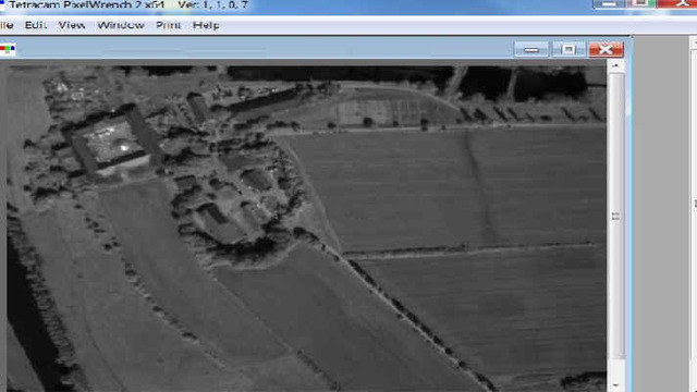
Additional ADC Reference
Information
Example
ADC Multispectral Images |
|
| |

|
|
| |

|
|
|
|
|

|
|
|