Tetracam Image File Formats and Capture Intervals


Tetracam Image File Formats


In order to create images that deliver consistently-reproducible and scientifically-valid results, every pixel in a Tetracam image is generated with high spectroscopic accuracy.  Radiation levels captured by Tetracam multispectral cameras are precisely represented by digital codes that are stored in three native file formats (8-bit Raw, 10-Bit Raw and 10-Bit DCM).  Each format is lossless providing maximum image fidelity.   Each is user selectable through camera menu configuration settings.  The software that is included with each multispectral camera, PixelWrench2, enables conversion of native file formats to standard image formats such as BMP, JPEG, PNG, WMF and TIFF.


ADC RAW files consist of collections of raw pixel values (digital numbers) and embedded data that includes a GPS sentence (if a GPS receiver was connected to the camera), exposure time and unit serial number. ADC DCM files comprise the same data plus image thumb-nails organized in a proprietary losslessly compressed format.


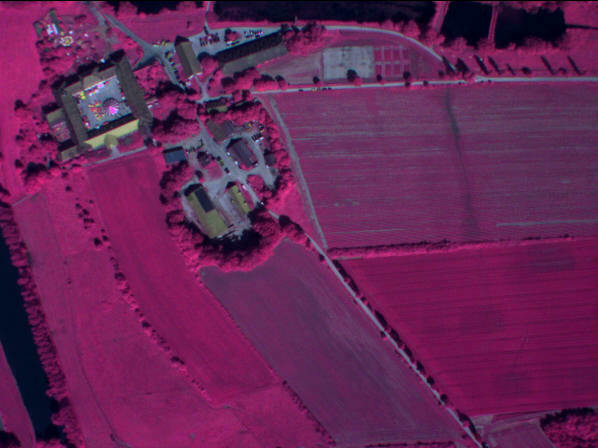
In RAW or DCM formats, the pixel values must be processed to yield a “false color” bitmap in which the received near-infrared radiation is placed on the red bit plane of the image, the received red radiation is placed on the green bit plane and the received green radiation is placed on the blue bit plane of the image. The resulting "False Color" image shows the magenta-colored vegetation familiar to most users of multi-spectral images (see example below). Once the false color 
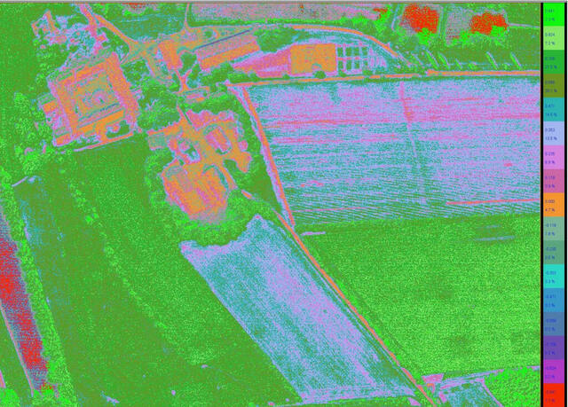
image is available, PixelWrench2 can extract images representing vegetation indices such as the Normalized Difference Vegetation Index or NDVI (see second example below).


Vegetation indices such as NDVI more clearly quantify the subtle variations in the colors that are present in an image.   PixelWrench2 enables users to select their own color values to represent each gradation in NDVI values in a legend that is shown immediately adjacent to the NDVI image.  The legend shows the NDVI values that each color represents and the percentage of the image that possesses that particular NDVI value.  This legend makes it easier for users to spot changes in NDVI values that occur in a field and are represented in images captured at different times.


Tetracam Mini-MCA systems also produce RAW and DCM files.  As each sensor is loaded with a single filter, Mini-MCA image files do not require color processing. The pixel values in Mini-MCA files represent the digital number produced by the sensor when exposed to reflected radiation of a specific center wavelength and bandwidth.  The amount of radiation captured (and so, the digital number stored for each pixel) depends upon the selected size of the lens aperture (f-stop) and/or the image exposure time. 


Mini-MCA systems may be equipped with an Incident Light Sensor that records the total amount of radiation that is illuminating the captured scene at the wavelengths monitored by the system.  PixelWrench2 may then be used to show images with pixel values that are expressed in terms of absolute reflectance values at those wavelengths (i.e., the fraction of incident radiation that is actually being reflected back to the multispectral camera for each pixel in the image) rather than in terms that are more susceptible to changes due to camera setting or ambient lighting variations. 


Tetracam Image Capture Time Intervals


The time required to capture and process digital images is proportional to their file size.  Each native ADC image is made up of 3.2 Mega-pixels arranged in a 4:3 aspect ratio of 2048 x 1536 pixels.  Each pixel in an ADC image possesses an 8- or 10-bit depth.  Each native Mini-MCA image is made up of 1.3 Mega-pixels arranged in a 4:3 aspect ratio of 1280 x 1024 pixels.  Each pixel in a Mini-MCA multispectral camera image also possesses an 8- or 10-bit depth. When aligned with images from other sensors in the Mini-MCA array, bit depths between 32 and 120 bits per pixel are attained. 


In order to accurately stitch images together, image mosaicking programs require adequate space for images to overlap. This introduces an important consideration when planning flights to capture multi-spectral imagery. 


Aircraft must not over-fly the start of the next image's overlapping edge along the line of flight.  For this reason,  flight mission plans must account for the time interval required by the camera to capture, process and store each image prior to triggering a new image.


The required time intervals between successive captures of full resolution images are shown in Table I below.  If these intervals are too long to allow the necessary image overlap required by image mosaicking software, this may be corrected by reducing aircraft speed or by flying the aircraft at a higher altitude (increasing the camera's field of view and so, the time required by the aircraft to reach the overlapping edge). 


Alternatively, this may also be corrected by reducing the time interval required by the camera to capture successive images for NDVI mapping.  This may be accomplished by configuring the camera to sub-sample each image at a lower resolution through the camera's configuration menu. The time intervals between successive image captures for sub-sampled images are shown in Table II below.


Table I

Approximate Time Interval Between Successive Image Captures for Full Resolution Images*


Tetracam System Model

Image Resolution

8-Bit Raw Image

10-Bit Raw Image

10-Bit DCM

ADC Micro

2048 x 1536 pixels

2.0 Seconds

1.5 Seconds

5.5 Seconds

ADC Lite

2048 x 1536 pixels

3.0 Seconds

5.0 Seconds

7.5 Seconds

ADC Air

2048 x 1536 pixels

3.0 Seconds

5.0 Seconds

7.5 Seconds

ADC FX

2048 x 1536 pixels

3.0 Seconds

5.0 Seconds

7.5 Seconds

ADC

2048 x 1536 pixels

3.0 Seconds

5.0 Seconds

7.5 Seconds

Mini-MCA

1280 x 1024

1.0 Second

2.0 Seconds

5.0 Seconds


 * Interval may vary with storage media


Table II

Approximate Time Interval Between Successive Image Captures for Sub-Sampled Images* 


Tetracam System Model

Image Resolution

8-Bit Raw Image

10-Bit Raw Image

10-Bit DCM

ADC Micro

1024 x 768 pixels

0.9 Second

0.7 Second

1.8 Seconds

ADC Lite

1024 x 768 pixels

1.0 Second

1.0 Second

7.5 Seconds

ADC Air

1024 x 768 pixels

1.0 Second

1.0 Second

7.5 Seconds

ADC FX

1024 x 768 pixels

1.0 Second

1.0 Second

7.5 Seconds

ADC

1024 x 768 pixels

1.0 Second

1.0 Second

7.5 Seconds

Mini-MCA

640 x 512

0.5 Second

0.5 Second

5.0 Seconds


 * Interval may vary with storage media


Example of High Resolution ADC RAW "False Color" Image Converted to Low Resolution JPEG Image


Example of Low Resolution NDVI JPEG Image Extracted from Above False Color Image